
News
Equipment Relocation, and installation.
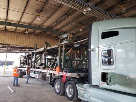
Recently, Crow was hired by a client in the Northwest that wanted to replace an outdated planer mill. The client had identified a planer line located in the Southeast and hired Crow as the principal consulting engineer and the contractor responsible for disassembling, relocating, adapting, and installing this system in their facility. To accomplish the task, Crow divided the project in several phases.
Read MoreNew Crow Engineering Southeast Office

This office has allowed us to significantly expand our Southeast presence and deepen our engineering and project management expertise. This commitment to the Southeast region has already greatly increased our ability to service both new and existing clients within the forestry and building products industries.
Read More