Improving productivity with PLC programming

Improving productivity with PLC programming

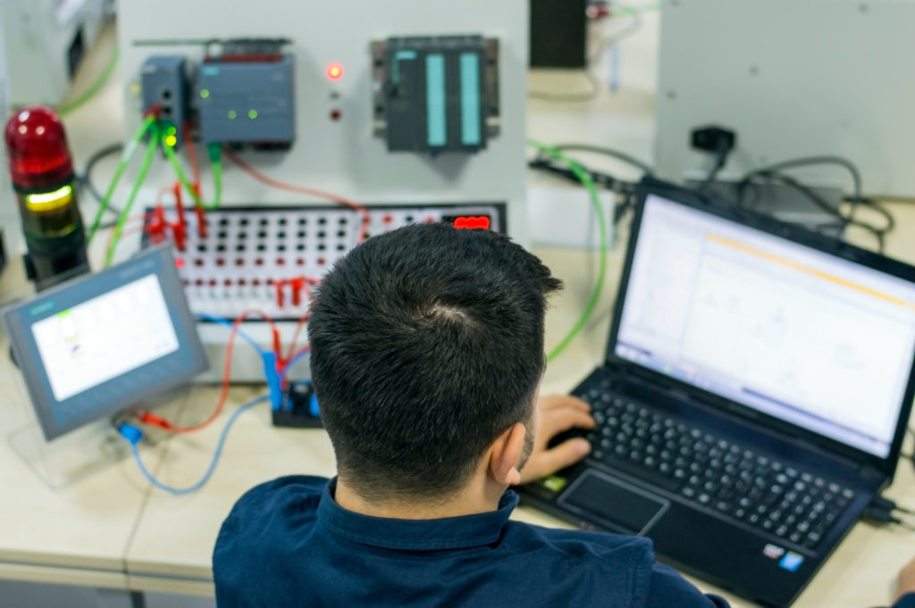
If you need to upgrade or improve your PLC systems, start by collecting detailed field notes of equipment, wiring, functions, etc. This will give you a detailed list of components that need to be supported by your PLC systems as well as catalog of necessary parts such as new control processors, modules, remote racks, motion control components, network switches, console components, and more. Another essential task to do before the configuration of an automated control system is PLC programming.
Read more about how your operation can improve productivity with PLC programming


Improving productivity with PLC programming

In simple terms, a Programmable Logic Controller (PLC) is a robust computer with a microprocessor – but without a keyboard, mouse, or monitor. It is used to control industrial equipment and monitor condition states regarding temperature, moisture, dust, and more.

A PLC uses protocols and ports to communicate with other systems. After receiving information from connected input devices and sensors, the PLC processes the data and triggers required outputs per pre-programmed parameters. Based on these inputs and outputs, the PLC monitors and records runtime data regarding machine productivity, temperature, and other parameters. It can also generate alarms when machine failure occurs and initiate automatic start and stop processes – just to name a few capabilities.

To interact with a PLC, users require a Human Machine Interface (HMI). These can take the form of touchscreen panels or simple displays that allow users to input and review PLC information in real time.

When Crow works with clients seeking to improve or upgrade their PLC systems, the first activity we propose is to conduct a PLC assessment to collect detailed field notes for equipment, wiring, functions, etc. The result of such an assessment is a detailed list of components to be supported by the new PLC system – along with a list of necessary parts such as new control processors, modules, remote racks, motion control components, network switches, console components, and more.

The critical importance of programming

Another essential task is PLC programming. A PLC program consists of a set of instructions, which represent the logic to be implemented for specific industrial projects and applications. At Crow, our PLC specialist and skilled industrial electricians provide essential programming services for new PLC, HMI, and motion control systems. We study existing programs to replicate functionality, write new logic based on existing systems, and design new HMI applications to replace existing implementations.

Proper PLC programming is essential for making equipment and operations faster, more efficient, and more cost-effective. Program functions include initiating the conditions for starting a specified task, executing interruptions, and handling errors. When programmed correctly, PLCs play a critical role in enabling automation, minimizing power consumption, increasing system control, keeping records, and redistributing the available workforce to increase productivity.

Our PLC specialists also have the skills and assistance of our engineering group at their disposal. They can quickly order up needed drawings (layout drawings, control power drawings, or I/O drawings to detail device connections to new PLC) or request project management to ensure vendors and contractors are on track and deadlines are met. We also have the resources to commission equipment – and we always stick around to train technicians and operators on how to get the most out of the new system.

Why a PLC upgrade?

If you deal with reoccurring equipment nuisance issues daily, there’s a good chance these can be resolved through minor changes in your PLC Logic. Your personnel may consider these nuisances to be a simple fact of life – but with some critical observations and the right information, Crow can help you illuminate the underlying cause standing in the way of improved productivity and operational efficiency.  

Let’s say you have a minor issue that causes your line to stop five times a day with a loss of two minutes each stop. Maybe this seems like something you can live with – but, assuming a seven-day operation, you’d lose 60 hours of production per year. When your PLC is not working properly or is down, your machines stop running – causing delays that reduce productivity and cut into revenues. Crow can help. Call (503-213-2013) or email Crow (inforequest@crowengineering.com) to schedule a consultation. Our PLC specialists can provide an assessment, programming, and recommendations to improve your process.

Why Is My Blow Detector Inconsistent?

Why Is My Blow Detector Inconsistent?

Other Blow Detectors Can’t Meet Performance Standards. The Reasons Are Clear.

There are two primary problems with ceramic crystal transducers used in blow detectors. The first is that they’re finely tuned devices (with a high Q factor) where the transmitter and receiver need to operate within in an exceptionally narrow frequency band. These devices tend to drift – and not necessarily together. Because of the narrow frequency requirement, a small amount of drift can have a dramatic impact on received energy. This causes the detector to trip on false positives – an expensive proposition for a plant.

The second problem has to do with resonant frequencies and broadband applications. A typical transducer includes a transmitter and receiver. A standard Miloptic transmitter produces a narrow band output targeted at frequencies in the 16-95khz range. The receiver – which is broadband over this range – is electronically narrow-banded later in the process. This allows the system to be tuned to a “sweet frequency” – one that is ¼ or ¾ wavelength in the material being inspected. At ¼ wavelength, or a multiple thereof, the material approaches transparency – making it much easier to penetrate. However, piezoelectric ceramic crystals do not like to be driven off their resonant frequency – and, therefore, are not effective in broadband applications.

I have encountered both of these problems based on decades of hand-on experience. In 1968, I worked with my team at Trienco – now Miloptic – to build and install the world’s first air-coupled blow detector. Initially it worked great – but when it was installed into a high-production mill, we started to see issues.

The ceramic crystal transducers in the initial design drifted – causing inaccurate positive readings. Our testing at the time showed that blow detectors with ceramic crystals will never deliver consistent results under high-production conditions. It took some time, but by mid-1973 we successfully developed our exclusive transducers without ceramic crystals. The Trienco 506 system was born.

Since then, we have successfully installed over 220 Trienco 506’s. We are extremely proud to report that many of them are still in service – after 30 years of operation. As technology improved and our engineering expertise has increased, we launched the 5600 and current 5700 product lines. The new 5700 series has been designed to integrate with Rockwell and other PLC solutions. It also provides solutions for many different panel types – in addition to flooring, gypsum, and siding. And best of all, Miloptic’s products are made in the USA.

Want to learn more about the differences between the Miloptic transducers and their ceramic counterparts used by most of our competitors? Feel free to call us at 503-213-2013 or email us at support@miloptic.com.

Specification and Design of Pre-engineered Metal Buildings (Part I)

Specification and Design of Pre-engineered Metal Buildings (Part I)

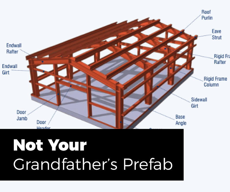
Pre-engineered metal buildings are common features in industrial settings. In fact, they have become common features in many types of construction from utilitarian sheds to keep out the elements to multi-story architectural buildings for just about any use. This is the first part of an article looking at specifying metal buildings for industrial settings.

Figure 1. Common Metal Building Components (image found on internet, creator unknown)]

The Basics

Pre-engineered metal buildings are metal building systems that have been commonly called pre-engineered. They go by a few common acronyms such as MBS (metal building systems), and PMB or PEMB (pre-engineered metal building). The term pre-engineered primarily grew from the idea that these metal building systems were designed and engineered for a set of pre-defined sizes and loadings prior to any customer order. These buildings can be quickly ordered, delivered, and erected on the customer’s site without the need for custom engineering. In a sense, these buildings might be considered kits. To fill an order, materials are pulled from common stock and delivered to the buyer. The building is then erected by a separate contractor.

Standard size metal building kits can be ordered from many supplier catalogs – with options for doors, windows, color, and more. One can find these kits advertised online or in magazines for use as small sheds or outbuildings. However, some engineering or customization may still be needed to accommodate certain site conditions such as wind speeds, earthquakes, or snow loads.

Most metal buildings ordered for industrial use require some form of additional special requirements such as customer-specified dimensions and design loads, and features such as cranes. For buildings in this category, building engineering and calculations are actually done after the building is ordered, and final structural sizes are not known until this effort by the vendor is complete.

Figure 2. Typical Metal Building Cross Section

Vertical Dimensions

It is common to specify the building width and eave height as shown in Figure 2. These dimensions set the outer limits and height of the building in a way commonly used by metal building manufacturers. The eave height is usually specified to the top of the roof purlin. An 8-inch purlin, placed on top of the rafter, is commonly used – although deeper elements can be selected based on the roof loading and deflection limits desired. Specifying the outer dimensions in this way allows the outer overall building size to be controlled, which is usually desired.

At the time of ordering, the clear height on the inside of the building may not be known since the final depth of the purlins and the rafter is based on the final calculations for the member sizes. This can pose a problem in some situations where large rafters drop a significant distance into the space inside. For example, it may be necessary to maintain a minimum clearance for storage racks or a piece of equipment inside the building. Mobile cranes are another item that requires minimum clearance to the lowest portion of the horizontal rafter.

In these situations, the required inside clear height of the building can be specified instead of the eave height in order to ensure the required clearance. In this situation, the eave height will vary based on the final determination of the rafter depth. Where there are building site limitations for both the minimum internal clear height and the maximum eave height (matching an existing building, for example), it may be necessary to contact a building vendor to ensure that the allowable rafter dimension can be achieved.

Forest Product Expo 2021

Horizontal Dimensions

The overall outside dimension of the building to the outside face of the horizontal wall girts is usually specified in order to control the overall size of the building similar to specifying the eave height. Wall girts are most commonly placed on the outside of the vertical column face as shown in Figure 2 at column line B. This allows for easier connection detailing to the face of the column and allows the girts to be overlapped creating a stiffer wall and allowing for a larger girt spacing.

Girts may be inset as shown at column line A in order to accommodate needs such as minimizing the overall outside dimension while minimizing intrusion of the column into the interior space. This option is usually more expensive for the steel building manufacturer although it has some benefits that can be considered. Where inside horizontal clearance is needed, but the building’s outside dimension is restricted, insetting the column into the girt space can make for a bit of extra width.

While wall girt size can vary, an 8-inch wide girt is common. Similar consideration may be needed regarding the horizontal clear space inside the building versus the overall outside dimension specified. This is because the wall girt can vary and more commonly the column dimension may not be known until after the building is ordered.

In many cases, it will be necessary to work with a metal building manufacturer prior to ordering to determine if the required dimensions can be achieved.

In the next newsletter we will describe the design criteria and specifications of the pre-engineered metal buildings. If you have any questions regarding this topic or need structural engineering, please contact our office to understand how we can help.


AIC Systems Still Up and Running After 30 Years

AIC Systems Still Up and Running After 30 Years

In 1973, Automation Industries Corporation (AIC, now Miloptic) developed blow detectors that used air-coupled ultrasonic nondestructive testing technology. Now, several of the systems – installed more than 30 years ago at panel and flooring facilities – are still up and running. These systems help manufacturers improve the quality of their products by:

  • Assuring internal bond quality at full process rates after the press, saws, or sander
  • Optimizing the recovery of good material from master panels containing defects
  • Optimizing pressing recipes
  • Eliminating delamination claims from the field
  • Reducing defectives and downgrades by early detection of process problems

Why are these systems still functioning and delivering value?

Mainly because they were carefully developed with embedded PCs to avoid obsolescence risk and with innovative technology to ensure immunity to the airborne interference sources. 

Sophisticated acoustic filters eliminate potential plant-ambient interference, resulting in high signal-to-noise ratios and accurate, reliable performance. Also, the Miloptic systems do not use ceramic crystal-based transducers to avoid sensitivity drift and inefficient coupling into air. Many air coupled ceramic devices were designed for use in burglar alarms and rudimentary piece counting applications, all of which do not have stringent requirements associated with nondestructively testing wood fiber-based products in a full industrial manufacturing environment. Transducers using ceramic piezoelectric crystals are sensitive to temperature variation, causing good panels to be identified as defective. Miloptic transducers are, at a minimum, five times as efficient at coupling ultrasound into and out of air when compared to ceramic crystal.

The quality and toughness of the steel scanner frame included design details such as easy access to transmitters and receivers. When transducers need to be replaced, the technician can remove them in less than one minute, making cleaning easy and efficient. The transmitter covers can be removed in seconds should they become damaged. During startup, mounting buckets are locked in place to ensure transducers are not later misaligned.

Almost fifty years and still going strong! Miloptic is committed to the ongoing development and production of durable, high-quality systems to serve the needs of the wood product industry for decades to come.

“Crow’s goal is to continue to be the first place mills turn to for help with improving their operations.  Traditionally this support has come from capital and maintenance project support.  This acquisition, and the recent addition of PLC and electrical capabilities now allows us to help our clients in optimizing their operations.   We are excited to have this opportunity with the AIC team and the 40+ years of experience they bring to the table!”

Hunter Wylie
Crow Engineering’s President