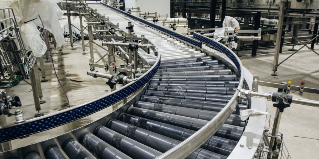
Pre-engineered metal buildings are common features in industrial settings. In fact, they have become common features in many types of construction from utilitarian sheds to keep out the elements to multi-story architectural buildings for just about any use. This is the first part of an article looking at specifying metal buildings for industrial settings.
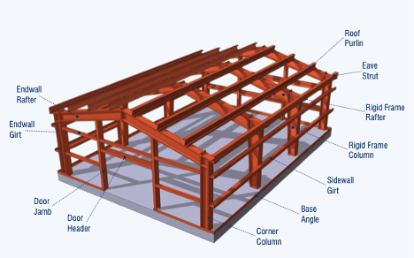
Figure 1. Common Metal Building Components (image found on internet, creator unknown)]
The Basics
Pre-engineered metal buildings are metal building systems that have been commonly called pre-engineered. They go by a few common acronyms such as MBS (metal building systems), and PMB or PEMB (pre-engineered metal building). The term pre-engineered primarily grew from the idea that these metal building systems were designed and engineered for a set of pre-defined sizes and loadings prior to any customer order. These buildings can be quickly ordered, delivered, and erected on the customer’s site without the need for custom engineering. In a sense, these buildings might be considered kits. To fill an order, materials are pulled from common stock and delivered to the buyer. The building is then erected by a separate contractor.
Standard size metal building kits can be ordered from many supplier catalogs – with options for doors, windows, color, and more. One can find these kits advertised online or in magazines for use as small sheds or outbuildings. However, some engineering or customization may still be needed to accommodate certain site conditions such as wind speeds, earthquakes, or snow loads.
Most metal buildings ordered for industrial use require some form of additional special requirements such as customer-specified dimensions and design loads, and features such as cranes. For buildings in this category, building engineering and calculations are actually done after the building is ordered, and final structural sizes are not known until this effort by the vendor is complete.
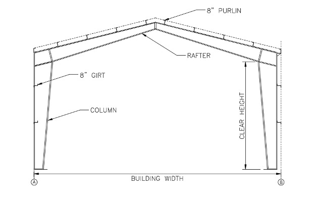
Figure 2. Typical Metal Building Cross Section
Vertical Dimensions
It is common to specify the building width and eave height as shown in Figure 2. These dimensions set the outer limits and height of the building in a way commonly used by metal building manufacturers. The eave height is usually specified to the top of the roof purlin. An 8-inch purlin, placed on top of the rafter, is commonly used – although deeper elements can be selected based on the roof loading and deflection limits desired. Specifying the outer dimensions in this way allows the outer overall building size to be controlled, which is usually desired.
At the time of ordering, the clear height on the inside of the building may not be known since the final depth of the purlins and the rafter is based on the final calculations for the member sizes. This can pose a problem in some situations where large rafters drop a significant distance into the space inside. For example, it may be necessary to maintain a minimum clearance for storage racks or a piece of equipment inside the building. Mobile cranes are another item that requires minimum clearance to the lowest portion of the horizontal rafter.
In these situations, the required inside clear height of the building can be specified instead of the eave height in order to ensure the required clearance. In this situation, the eave height will vary based on the final determination of the rafter depth. Where there are building site limitations for both the minimum internal clear height and the maximum eave height (matching an existing building, for example), it may be necessary to contact a building vendor to ensure that the allowable rafter dimension can be achieved.
Horizontal Dimensions
The overall outside dimension of the building to the outside face of the horizontal wall girts is usually specified in order to control the overall size of the building similar to specifying the eave height. Wall girts are most commonly placed on the outside of the vertical column face as shown in Figure 2 at column line B. This allows for easier connection detailing to the face of the column and allows the girts to be overlapped creating a stiffer wall and allowing for a larger girt spacing.
Girts may be inset as shown at column line A in order to accommodate needs such as minimizing the overall outside dimension while minimizing intrusion of the column into the interior space. This option is usually more expensive for the steel building manufacturer although it has some benefits that can be considered. Where inside horizontal clearance is needed, but the building’s outside dimension is restricted, insetting the column into the girt space can make for a bit of extra width.
While wall girt size can vary, an 8-inch wide girt is common. Similar consideration may be needed regarding the horizontal clear space inside the building versus the overall outside dimension specified. This is because the wall girt can vary and more commonly the column dimension may not be known until after the building is ordered.
In many cases, it will be necessary to work with a metal building manufacturer prior to ordering to determine if the required dimensions can be achieved.
In the next newsletter we will describe the design criteria and specifications of the pre-engineered metal buildings. If you have any questions regarding this topic or need structural engineering, please contact our office to understand how we can help.
Who are we?
Crow Engineering is a multi-discipline consulting engineering firm serving mechanical, structural, and civil engineering needs for a variety of industries.
Engineering Services
Our Clients


the crow connection
Recent News
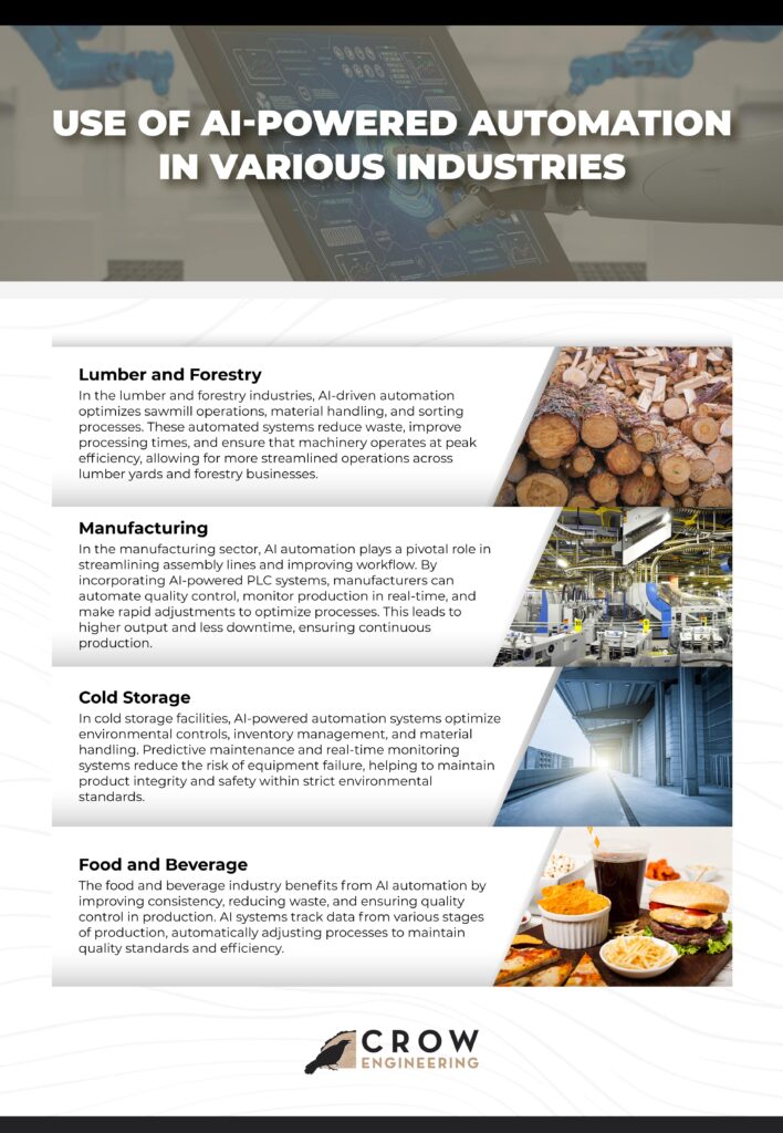
The Crow Connection delivers high-level insights on engineering, automation, and process optimization, helping you drive efficiency and innovation. Covering topics like AI-powered automation, manufacturing strategies, and industrial process improvements, it’s a must-read for leaders seeking a competitive edge.