

Structures and equipment don’t last forever. At some point, they begin to exhibit signs of wear and tear. Eventually, you need to take action. Which is what ‘brownfield” plant modernization is all about. There’s a lot of value in the equipment you already have – and with plant modernization, you can keep on generating value for years to come.
Read More
In the first part of this article, we looked at the basics and dimensions of metal buildings for industrial settings. In this second part of the article, we explain the design criteria and specifications of pre-engineered metal buildings.
Read More
Pre-engineered metal buildings are common features in industrial settings. In fact, they have become common features in many types of construction from utilitarian sheds to keep out the elements to multi-story architectural buildings for just about any use. This is the first part of an article looking at specifying metal buildings for industrial settings.
Read More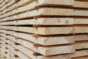
Crow has helped customers save millions of dollars in capital expenses by re-purposing current facilities and equipment on site. If you’re in the lumber business, it’s hardly news that demand has been outstripping supply – largely due to a pandemic housing boom that few saw coming. With new home building reaching a 15-year high, demand for new building materials such as 2×4 lumber is through the roof.
Read More
Keep the risk low, keep employees safe, and keep operations up and running – which keeps the revenue flowing.
Read More
Choosing the right partners to support your project often determines the success of that project. What’s needed are vendors with subject matter expertise and a proven track record of success.
Read More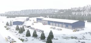
Designing buildings to stand up to the elements requires detailed site analysis to determine weather patterns, climate, soil types, wind speed and directions, heat, path of the sun, and more. Solutions involving insulation, vapor barriers, and air barriers will vary radically depending on whether the site is in the cold and snowy north, the hot and humid south, or the arid desert.
Read More
Recently, Freres worked with Crow Engineering to design an open-sided structure using its MPP product. The aim of the project was to infill a space between two manufacturing buildings at the Freres Plant 3 mill in Mill City, OR.
Read More
Two players. One chess board. One move yields a countermove – attack and defend, strike and counterstrike. Warring adversaries fight it out by the rules of an ancient game. There’s a quiet but palpable tension in the room. Then a single word breaks the silence: “checkmate.”
Learn how Crow Engineering brought chess into the office.
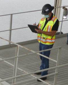
At Crow Engineering, relationships with customers last for years. One company – a long-term customer – recently engaged us to review ways to increase the productivity of its lumber manufacturing process. To assess and identify improvement opportunities, we conducted an efficiency study of the company’s log infeed and breakdown systems.
Read More